
Executive Summary
Infiltration ditches are one form of rainwater harvesting that uses underground trenches to absorb rainwater, store it temporarily, filter it naturally and finally return it to the soil as pre-cleaned seepage water. Infiltration trenches are therefore very valuable for closing natural water cycles in areas with sealed surfaces. The more technical use of such systems is to buffer heavy rainfall within a short period of time, to avoid flooding of the ground and entering of water inside buildings.
This factsheet describes modular “building-set”-type of rainwater infiltration ditches that are made of hard plastic and installed underground. They function as buffer storage for rainwater collected from available roof areas before infiltrating it into the underlying ground zone, from where it can enter the groundwater. Especially in densely built urban areas such high-performance modular systems show advantages over conventional infiltration ditches such as their larger storage capacity that reduces space and excavation requirements; or their high load-bearing capacity that also allows installations under busy roads or in high depths.
The modules can be assembled in various combinations depending on the particular needs and conditions on-site.
Input/Output/Removal of
| Input: | Rainwater |
| Output: | Groundwater recharge |
| Removal of... | Fine dust, leaves, branches, plastic parts as well as oils and other small elements |
Design considerations
As Kreta is a planning office for complete landscape architecture projects, we draw our knowledge from a large repertoire of experience in the development of such projects and also the text below is built on practical expertise rather than literature.
There are of course many different ways of collecting and conserving surface runoff rainwater for groundwater recharge. In this factsheet we focus on “building-set”-type modular, underground infiltration ditch systems.
Modular rainwater infiltration ditch systems usually collect water from roof runoff and generally consist of the following main components:
- a piping system made of plastic, concrete or other materials that connects the roof’s gutter downpipes with the infiltration ditch
- a sedimentation unit, also referred to as cleaning shaft, for roughly cleaning out dust, oils, leaves, and other small parts before the water enters infiltration ditches
- usually box-shaped plastic storage elements, also referred to as modular fillers, that can be put together and/or stacked to blocks (infiltration ditches) with one or several layers
- a control shaft, also referred to as inspection shaft, for accessing the inspection channels integrated in the infiltration ditches for monitoring and cleaning purposes.
In order to promote the function of the sedimentation unit, the dimensioning of the piping system has to fit to the sedimentation unit’s cleaning capacity. Thus, depending on the amount and cleanliness of the expected rainfall there is a maximum of roof surface that can be connected to each sedimentation unit. Also, the diameter selected for the inlet pipes to the sedimentation units should assure a certain flow is not exceeded. It is important to note that fixing the slopes of roofs and taking into account the location of rainwater outlets prior to system installation, can considerably lower the costs for the piping.
The sedimentation unit is a shaft module that allows access for inspection, has an integrated sludge chamber (also called mud flap) located in the lower part of the sedimentation unit and a volume for liquids. It has to be assured that as little dirt as possible gets into the infiltration ditch modules.
The infiltration ditch modules are normally reinforced by side wall grids and additionally completely covered with a geo-textile filter fleece and protected by an additional, surrounding sand layer. The geo-textile assures no soil material enters and blocks the infiltration modules. The lower sand surface serves as a bedding and allows the modules to be laid horizontally. The excavated area should be flat / even, so no water accumulates underneath the storage elements and silts up the underlying soil material.
In a modular system, control shafts can be installed at any point a of the frame of modules. Ideally, the control shaft provides convenient access from above for inspection and cleaning purposes. The control shafts’ height is determined by the number of layers of the connected infiltration channels and can be extended layer by layer as the infiltration ditch is constructed. The control shaft should be equipped with an extension pipe that connects to an emergency overflow, so in case the infiltration ditch has been used to its full capacity, excess water flow can be discharged into a storm water sewer or other receiving body. In modular systems, the control shaft module is supplied with all necessary components and assembled on site. The control shafts can be strengthened on the surface by concrete rings to provide additional protection against overlying loads like vehicles.
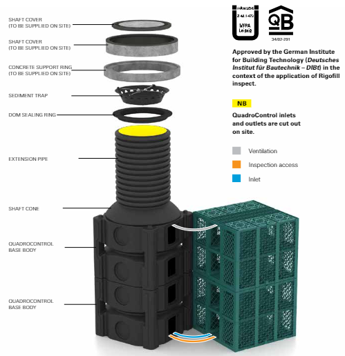
Figure 1. Example of a maintenance shaft (left side) that is used for maintenance and inspection of modular fillers. Source: FRAENKISCHE (2021)
Before infiltrating the water into the ground water body, passage through a filtering layer is required – in accordance with the legal requirements to be met for infiltration.
Depending on the particular set-up, the system can be equipped with a digital weather station for monitoring of the rainwater quantities and a sensor installed in an inspection shaft to provide information on the current storage capacity. This allows to determine the exact rate of rainwater discharged into the groundwater body.
In the following we describe some of the main requirements that have to be met when installing a modular infiltration ditch system: (1) A minimum distance from buildings and other structural objects, calculated by multiplying the building depth in the ground with a factor of 1.5. (2) Subsoil conditions that are unfavourable for infiltration, so the rainwater can be retained, and infiltration is drastically delayed so it can be used to substitute pumping of groundwater. (3) The distance between infiltration system and the groundwater body must be at least one meter (4) In order to guarantee trafficability, the upper edge of the infiltration trench must be at least 80 cm below the upper edge of the pavement. The structure in between must be adapted to the expected loads the system will be exposed to.
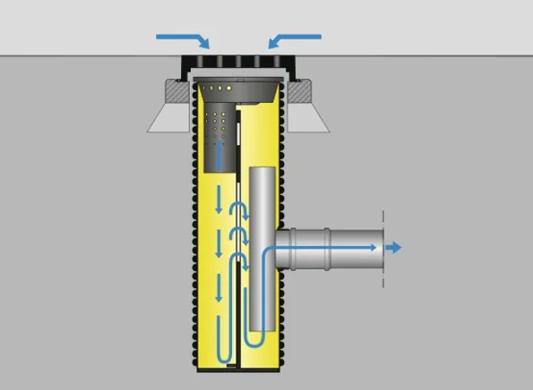
Figure 2. Example of a cleaning shaft of the manufacturer. Source: FRAENKISCHE (2022a)
Suitability
Applications/contexts
Generally speaking, modular rainfall infiltration systems are most appropriate for densely built urban areas. First of all, this is due to that fact that in such the contexts surfaces are heavily sealed and natural drainage, respectively retention capacity, is insufficient, making open spaces very prone to flooding. Also, especially in densely built urban areas underground land is very valuable, thus the reduction of space and excavation volume requirements is advantageous. A further aspect that makes modular systems specifically interesting for urban areas are their load-bearing capacity. The systems can even be installed under busy roads, up to a loading capacity of trucks up to 60 tons or in high depths. If dimensioned and installed well, the systems are robust and durable, as they are installed underground. However, in case of insufficient dimensioning of the infiltration trench volume leading to flooding or lacking maintenance, complications and sometimes complete failure of the systems may occur.
Manufacturers of plastic water collection and control shaft for modular infiltration systems tend to be concentrated in the European market even though the technology is easy to transfer. Also, depending on the intended use of the collected rainwater (e.g.: groundwater recharge, water retention for subsequent use for water treatment), the components could also be made of concrete, bricks, or other plastic components. Other construction materials like the geo-textile fleeces and foils and concrete rings can be sourced in India or China.
The infiltration system per se does not require a power supply. However, digital monitoring and maintenance equipment require a reliable power supply.
Operation and Maintenance
Since there is a risk of clogging or silting up of the rainwater harvesting system, regular monitoring, professional cleaning, and regular maintenance are essential to assure proper functioning and prevent failure of the different system components.
An initial inspection should be foreseen for right after the construction phase. It is precisely during this period that small parts and other contaminants get into the infiltration ditch.
After that, in Europe, the systems are checked twice a year and cleaned accordingly after evaluation. In other regions, i.e. India, where monsoon periods prevail, the system should be checked more frequently during such critical periods where heavy rainfall occurs. Inspection is carried out through the control shafts, or ideally, with a mini camera. Depending on the design of the infiltration/storage blocks, some designs foresee corridors so that it is possible to drive through with a camera. If they are exposed to a lot of dirt, a camera inspection of the modules is recommended.
he mud flap (sedimentation module) can be cleaned manually or with an automatically operated cleaning pump. Cleaning is carried out by vacuuming the dirt trap of the cleaning shaft and should happen regularly and more frequently during the rainy season. The whole body of the rainwater harvesting system should be cleaned after the monsoon period using the sewer flushing technique/high-pressure flushing. Exact instructions on cleaning and maintenance techniques to be used depend on the manufacturer of the modules.
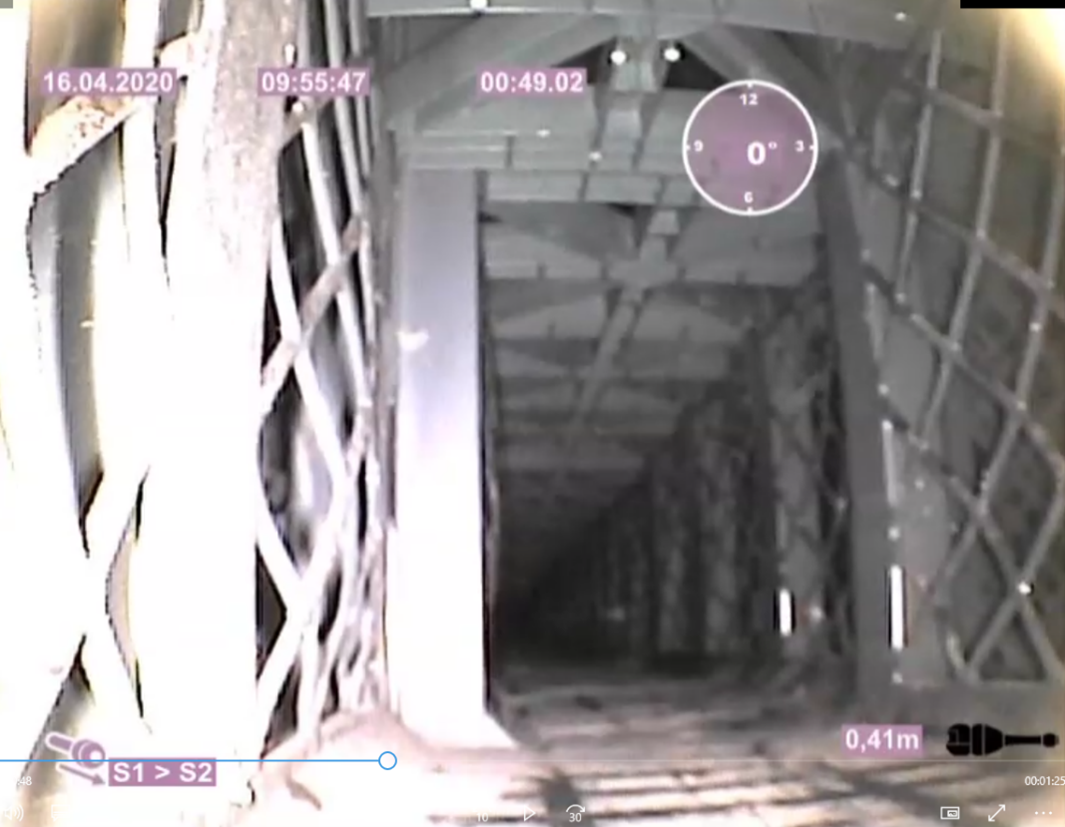
Figure 3. Camera shot of a storm drain system at a Hotel on Stralauer Platz in Berlin. The infiltration ditch is installed in the courtyard and collects rainwater from the roof and terrace areas. Source: ODENTHAL (2020)
Experiences in India
The use of infiltration trenches or -areas for rainwater retention has been known and technically applied for more than 100 years in various regions of the World. In India, larger rainwater retention basins are also known and used.
Several rigs of modular plastic rainwater harvesting systems have already been installed in the region of New Delhi and most likely also in other parts of the country. A detailed review of previous experiences with systems of different manufacturers cannot be provided. Also, as set-up of the rainwater harvesting system are site specific, it is difficult to give a general cost estimation.
Typically, in India, installing a water harvesting system in a building would cost between Rs 2,000 to 30,000 (23.4 - 350.1 €) for buildings of about 300 sq. m. Costs for plastic tanks available as finished products to be used in various capacities range from Rs 2/litre to about Rs 3.5/litre (CSE, n.d.).
As mentioned above, the technology is widespread and there are also far more cost-effective systems in terms of function. However, a great advantage of this particular type of modular system is the flexible and adaptive design, which allows the systems to be used again and again and to be re-installed, where the shape and positioning can be used as desired.
Experiences Globally
In Germany, a system plus installation is associated with relatively high acquisition costs. At the moment this factsheet was compiled (2021), 1 m2 of gross volume costs between 390 - 420 € on the Berlin market. The price results from several of our realised construction projects in 2020-2021.
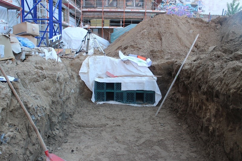
Figure 4. Rainwater harvesting system at a Hotel in Berlin implemented by Kreta in cooperation with Fränkische products. Source: ODENTHAL (2019)
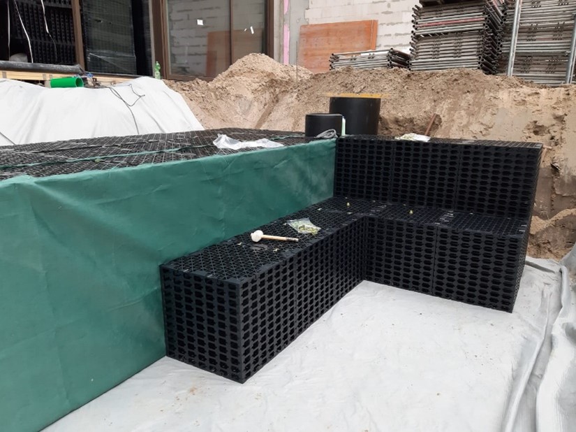
Figure 5. Rainwater harvesting system at an office backyard in Berlin implemented by Kreta in cooperation with Enriges products. Source: ODENTHAL (2020)
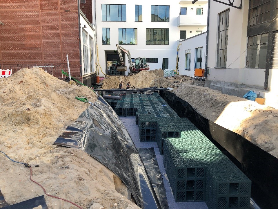
Figure 6. Rainwater harvesting system at backyard of the old post building in Berlin – Kreuzberg, implemented by Kreta in cooperation with Fränkische products. ODENTHAL (2020)
KRETA: Underground Rain Water Harvesting System
This presentation offers a broader view on Underground Rain Water Harvesting System
ODENTHAL, M. (2023): KRETA: Underground Rain Water Harvesting System. Training Program on Sustainable Natural and Advance Technologies and Business Partnerships for Water & Wastewater Treatment, Monitoring and Safe Water Reuse in India . PDFTraining Session Plan - Underground Rain Water Harvesting System
Training session plan on undergroung Rain Water Harvesting System
ODENTHAL, M. (2023): Training Session Plan - Underground Rain Water Harvesting System. Training Program on Sustainable Natural and Advance Technologies and Business Partnerships for Water & Wastewater Treatment, Monitoring and Safe Water Reuse in India . PDF